Effect of spurious resonant modes on the operation of radial mode piezoelectric transformers
If you would like more information on this topic, please click here for contact details Click here to download the paper presented at PCIM 2018This work analyses both the intentional and unwanted resonant modes of radial mode piezoelectric transformers (PTs). Initially, finite element analysis is performed to discover the type of spurious modes prevalent is radial mode PTs. From this, analysis is performed on these modes and a relationship between resonant frequency and geometry is found. The effect of spurious modes on the efficiency of a typical PT is simulated using an equivalent circuit model in LTSpice and Simulink. A number of design rules are generated based on the findings. Results show that, in most cases and by careful design, spurious modes can be avoided.
Piezoelectric transformer characterisation
In order to analyse the spurious modes that occur at frequencies near that of the radial vibration mode, their vibration shape must be determined. An eigenfrequency study was performed in COMSOL on a simplified 2D axisymmetric model of a piezoelectric transformer, with a radius of 9mm, a thickness of 3mm and made from PZT-5H. The first 4 vibration modes were recorded.(0,1) Mode
Radial Mode
(0,2) Mode
(0,3) Mode
Displacement of a circular PT under a number of vibration patterns
(Naming convention is (d,c) where d is the number of nodal diameters and c is the number of nodal circles)
Determining resonant frequencies of flexural modes
In order to optimise the design of a PT for minimum interference from spurious modes, the relationship between the geometry and material properties, and resonant frequency must be evaluated.Thoretical Analysis
Due to the complexities involved with generating a relationship between resonant frequnecy, material properties and geomertry, inital work was done starting from basic theory. To start, the PT was modeled as a single disk made from elastic material, which vibrates freely. This allows some assumptions were made based on the Kirchoff thin plate model. Mainly, that the radius is much greater than the thickness of the device, thus allowing certain stresses to be equal to zero simplifiing the analysis.
From this information, and analysing the forces on the vibrating disk the general equation for flexural motion can be developed: $$ D{\nabla}^4w + \bar{\rho}\frac{\partial^2 w}{\partial t^2} = 0 $$ Where $D = \frac{Yh^{3}}{12(1-\sigma^{2})}$, $Y$ is the Youngs modulus, $\sigma$ is Poisson's ratio, $w$ is the transverse displacement and $\bar{\rho}$ is the mass per unit area.
The general soluation to this equation (assuming displament at the center of the device is finite): $$W(r, \theta) = (A_{d}J_{d}(\lambda) + B_{d}I_{d}(\lambda))\cos(d\theta)$$ Where: $ \lambda^{2} = \sqrt{\frac{\bar{\rho}}{D}}fr^{2} $
By applying boundry conditions for a freely vibrating disk in terms of the bending moment and Kelvin-Kirchoff edge reaction, soluation for lambda can be found for each vibration modeFinite Element Simulation
Due to the complexities involved, exact analytical solutions can only be solved in 2D. In order to accurately solve this type of problem, a FEM should be used. Another advantage of finite element analysis (FEA) is that a PT can modelled as a number of separate layers rather than 1 disk, further improving accuracy. To investigate the relation between device geometry and resonant frequency of the flexural modes, a number of PZT-5H based devices will be simulated in COMSOL, with radii varying between 5 and 14mm and thicknesses between 1 and 5mm. In order to be able to relate the results to other material types and to the results achieved through the analytical method, the resonant frequencies will be converted to the ‘non-dimensional’ frequency.Results
To visulise the results the values of lambda will be plotted for both the FEA and analyitical models. The theorietical model states that lambda will be constant for all devices but due to the simplicfications we made (assuming radius>>thickness) this will only be true for large radius/ thickness ratios. Thus it is found that the value of lambda will be constant for any size device, so long as the radius/thickness ratio is constant. So the reuslts will be plotted against the ratio of raidus/thicknes.
2 Layer PT - Even layer thicknesses
The figure below shows the distrbution of lambda with radius/thickness for a 2 layer device with even layer thicknesses.
Variation of lambda with the ratio of device radius to thickness
As the FEA also finds the radial mode frequency this can also be plotted, allowing comparison between where the modes occur. For example, we know that the (0,2) mode crosses with the radial mode at the radius/thickness ratio of 4.66 and this is undesirable as this would cause problems as they would have resonant freqiencies in close proximity. Similarily with a radius/thickness ratios of 1 and 12, crossing with the (0,1) and (0,3) modes respectively.
For an ideal design we would design our PT to have a ratio of radius/thickness of either between 2-3 or 7-10, to ensure spurious modes has resonant freqencies far away from the radial mode.
2 Layer PT - Uneven layer thicknesses
Due to the increased design complexity FEA models allow, further analysis can be performed to understand how lambda changes for more typical PT designs.
Variation of lambda with the ratio of device radius to thickness
Mulitple Layer PT - Even layer thicknesses
In many cases, more than two layers will be required to achieve the desirable turns ratio.
Variation of lambda with the ratio of device radius to thickness
Mulitple Layer PT - Uneven layer thicknesses

Variation of lambda with the ratio of device radius to thickness
Implications of spurious modes
In some cases, choosing an optimal radius/thickness ratio for avoiding spurious modes is not always possible. In these cases it's important to understand how these modes affect the performance of the PT from both a mechanical and electrical perspective.
Physical effect of spurious vibration on the radial mode
To understand why it's important to avoid interaction between modes, a PT was be designed with a radius of 9mm and a thickness of 2.2mm. This gives a PT with the radial mode and 2nd flexural mode withinRadius 9mm, Thickness 2.2mm
Radius 9mm, Thickness 3.6mm
Showing the difference in quality of radial vibration, left with (0,2) mode in close proximity to the radial and right with the radial mode perfectly interbetween the (0,1) and (0,2) modes.
When the a spurious mode occurs at a frequency close to the radial mode, the radial vibration under normal opperation is sub-optimal with a flexural component too it. In a real PT this is likely to cause increased damping especially when the device is mounted to promote ideal radial vibration and poor electromechnical coupling.
Effect on electrical efficieny
To fully understand the effect that spurious modes have on the normal operation of a radial mode PT the efficiency will be analysised. It is well known that spurious modes have a derograratory effect on efficiency its important to understand the factors that cause this, in order to limit their effect.
Inital testing
In order to understand what happens when modes interact, a LTSpice simulation was performed on the extended Mason equivlent circuit model of a PT, as shown below.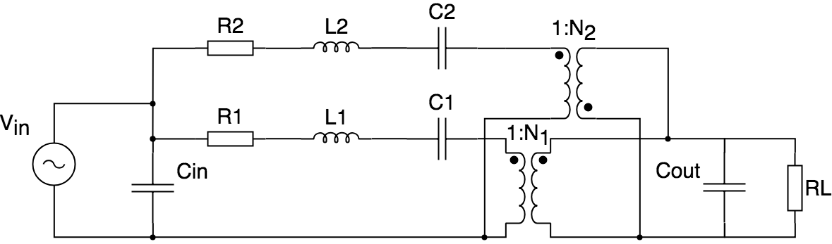
Mason equivlent circuit model of a PT, with 2 branches, 1 radial and 1 spurious
Varietion of efficiency with frequency for a PT with a radius of 9mm and thickness of 3mm
The most interesting feature of the results is the point in which the efficiency approaches 0%. It is important to consider why this occurs and the factors affecting the specific frequnecy and the spread of frequency affected in order to ensure high efficiency at the raidal mode.
Determining frequency of this condition
Firstly, a time domain simulation of the equivalent circuit at this frequnecy is performed to analyse what happens.At this frequency the magnitude and phase of both the radial and spurious RLC branches are approximatley equal. Due to the phase shift in the spurious equivalent transformer, then the current is equal in magnitude and opposite in phase in each branch, thus current circulates though the branches and no current reaches the output capacitor or load.
By summing currents at the output node and assuming the condition $I_{RLC_1} = -I_{RLC_2}$, an equation can be found for the frequency that this condition is true at interms of equivalent components.
$$\omega = \frac{1}{2}\cdot\,{\frac {\textrm j{\it C_1}\, \left( {\it R_1}-{\it R_2} \right) {\it C_2}+ \sqrt {-{\it C_1}\, \left( \left( \left( {\it R_1}-{\it R_2} \right) ^{ 2}{\it C_2}+4\,{\it L_1}-4\,{\it L_2} \right) {\it C_1}-4\,{\it C_2}\, \left( {\it L_1}-{\it L_2} \right) \right) {\it C_2}}}{{\it C_1}\,{\it C_2}\, \left( {\it L_1}-{\it L_2} \right) }} $$
$$\omega \approx \pm \sqrt{\frac{(C_2 - C_1)}{C_1C_2(L_1-L_2)}}$$ From the equation above, its apparant that this frequency is controlled by L and C in both branches. In order to fully understand
Results
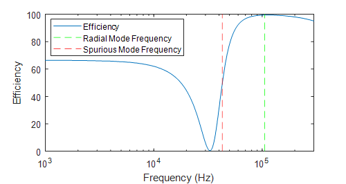
Initally, a simulation was performed to analyse the effect of the values of L/C in both braches. After inital testing it was belived that the ratio of the Q factor's affected the distance that the spurious mode must be from the radial mode in order to have no effect on efficiency. Due to the equation found ealier, it was then understood that it was due to the ratio of the values of L/C in both branches.
Variation of efficiency loss with proximity of spurious mode to operation frequnecy (slightly above radial resonance) and change in the ratio of spurious tank inductance to capactance with respect to the inductance to capactirance ratio in the radial mode. The damping in the spurious mode is at 300 $\Omega$
In order to observe how the spurious mode damping effects the results, a second simulation was performed varying the resistance for a fixed ratio of L/C in the spurious mode and the radial mode.
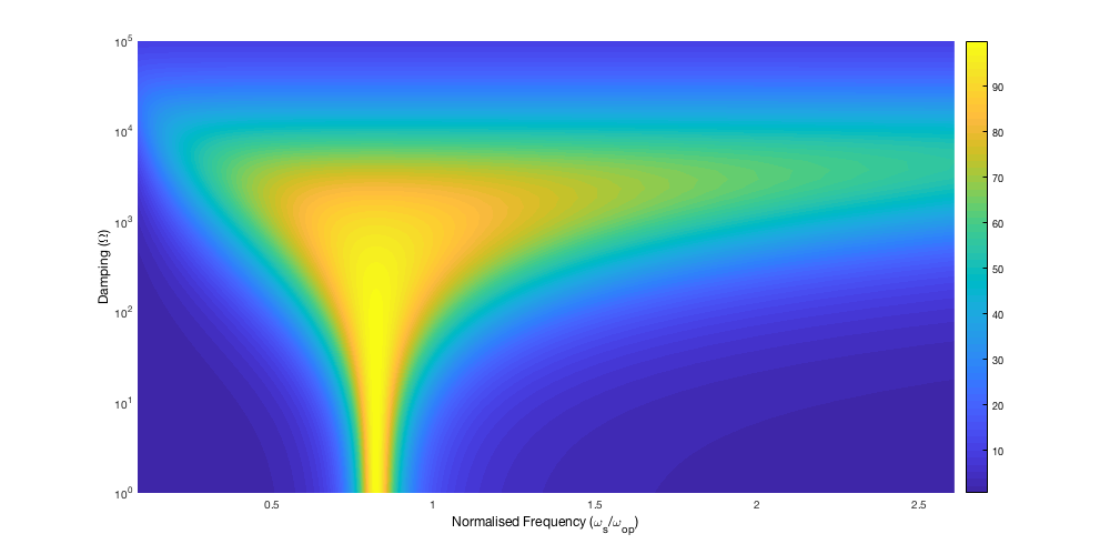
Variation of efficiency loss with proximity of spurious mode to operation frequnecy (slightly above radial resonance) and change the the values of the spurious mode damping. The ratio of spruious to radial L/C is fixed at 1.
Design Rules
The analysis presented in this paper highlights some of the important factors to consider when designing PTs in order to reduce the effect of spurious modes. Firstly, the best method of reducing the effect of spurious modes is to design the transformer such that the resonant frequencies of spurious modes are as far from the radial mode as possible. Avoiding radius and thickness values that give a ratio of close to approximately 1, 4.667 or 12 is necessary. If values of radius and total thickness are chosen such that their ratio is approximately 3 or 8.5, the radial mode frequency will occur directly in-between two unwanted modes.
In some cases, this will not be possible and so a number of other factors need to be considered. Ideally minimal or maximal damping is required in the spurious vibration, limiting the range of frequencies affected by this mode. Damping can be reduced through a number of methods such as, high Q materials, quality manufacturing and appropriate mounting. A final consideration is to design the device to have a much larger L/C ratio in the spurious mode than in the radial mode. This can be achieved by choosing a design that has a large ratio of radius to thickness and is also large in radius. For example, a device with a radius/thickness ratio of 1 has a relative L/C ratio much less than a device with a radius/thickness ratio of 5. Also a device with a radius of 5mm and thickness of 1mm has a lower relative L/C ratio that a device with a radius of 15mm and thickness of 3mm. 8. Conclusions The work presented in this paper is an initial analysis of where spurious modes occur in piezoelectric transformers and investigates the effect they have on performance. It has been shown that by careful geometric design, the effect of spurious modes can be reduced or in some cases eliminated. A number of design rules have been presented, as to reduce the effect of spurious modes. Although, due to the number of independent parameters involved, it isn’t possible without FEA to determine if the effect of a spurious mode is completely suppressed. In almost all cases designing a transformer to the rules presented, will prevent deleterious effects.
