RadPTDesigner
RadPTDesigner is a program for helping to design radial mode piezoelectric transformer resonant inverters. The user enters a power supply specification and then empircally tunes their design to obtain accept input impedance and zero voltage switching characteristics. The software was written as part of the ESPRC sponsored FPeT: Framework for designing piezoelectric transformer power supplies research project. Before describing how to use the software a brief review of piezoelectric power supplies is provided and the user is encouraged to read through the cited publications for further details.
Radial mode piezoelectric transformer power supplies
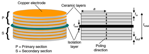
Similar to conventional magnetic induction transformers, radial-mode piezoelectric transformers (PTs) consist of a input (primary) section and an output (secondary) section.
They are constructed from a stack piezoelectric discs and they resonate with high efficiency when driven at the radial-mode. The figure below shows a typical radial-mode PT
with the primary section and secondary section separated by an electrical isolation layer. The primary and secondary sections consists of nin and nout layers of
piezoelectric discs, respectively. Each disc is electrically poled in a specific direction as indicated by the vertical arrows.
Electrical connection between the layers is made using copper electrodes.
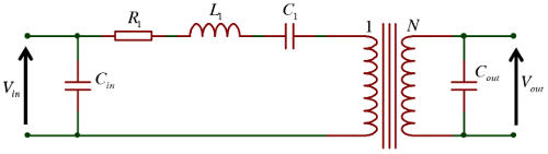
Being a resonating ceramic structure, the PT can be conveniently represented by Mason equivalent where Cin and Cout represent in the input and output capacitances,
L1 and C1 model the radial-mode resonance and R1 captures the damping/loss. The turn-ratio is captured by the ideal transformer with a
ratio N=Nin/Nout. Further details regarding the modelling of radial-mode PTs can be found in A Lumped Equivalent Circuit Model for the Radial Mode Piezoelectric Transformer.
In order to produce the most cost efficient power supply, PTs are usually driven by an inductor-less half-bridge circuit as shown below. Dead-time is essential in a half-bridge circuit to ensure a shoot-through
event caused by simultaneous conduction of the MOSFETs T1 and T2 is avoided.
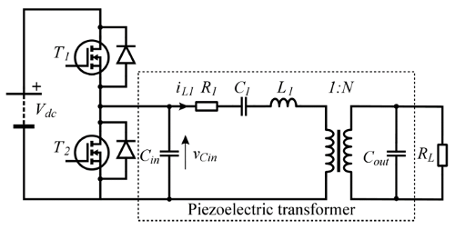
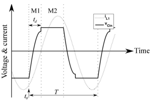
During the dead-time interval the MOSFETs are off and so iL1 flows through Cin. If T2 was on immediately prior to the dead-time, then
vCin will charge in a positive direction with a cosine wave shape. If the conditions are correct, then by the end of the dead-time interval VCin will exceed
the DC input voltage (Vdc). This means that MOSFET T1 can be turned-on at the end of dead-time under a condition known as zero voltage switching (ZVS). Since PTs feature a
relatively large input capacitance care must be taken to ensure ZVS can be achieved under all operating conditions. If the dead-time is too short or Cin is too large then vCin<Vdc
and so as T1 switches on the remaining charge present on Cin is discharged into the MOSFET incurring unnecessary switching losses, as shown below by the discontinuity at the end of the
dead-time interval td.
In Critical design criterion for achieving zero voltage switching in inductor-less half-bridge driven piezoelectric transformer based power supplies we demonstrated a critical relationship between the input and output capacitance, turn ratio, operating frequency and dead-time that ensures ZVS can guaranteed. Critical criterion can be stated as follows:
- Ensure the PT input-output capacitor ratio meets the following condition
- Set the operating frequency to the resonant frequency
- Synchronise the MOSFET turn-on signals to the zero crossing of the resonant current iL1
- Set the MOSFET on time to 90° or ton=0.25/f0
- Set the half-bridge dead-time to 90° or td=0.25/f0
RadPTDesigner - How to use
The screen is divided into two areas with Design specification on the left hand side and graphical results on the right. The Design specification section is divided into several sections: 1. Power supply specifications, 2. Material parameters, 3. Radius, 4. Initial design and 5. Refine design
For a specific design the user enters:
- a power supply specification which consists of the input and output voltage and power rating
- piezoelectric material parameters
- radius
The Refine design box allows the user to manually adjust the geometry of their design by specifying the radius and the number and the thickness of primary and second layers.
The Impedance displays the estimated input impedance spectrum of the PT. The ZVS profile tab provides information regarding the ZVS capabilities of the design.
is the ratio of the input capacitor at the end of the dead-time interval to the DC input voltage. A value
greater than 1 (Kzvs>1) indicates ZVS is achievable. A surface is shown as a function of the normalised operating frequency and load factor M=ω0CoutRL.
A contour line is drawn on the surface representing K
If you encounter any problems with the use of this software then please contact the author using m.p.foster@sheffield.ac.uk.
Disclaimer
RadPTDesigner is software for designing radial mode piezoelectric transformer resonant inverters. No warranty regarding the accuracy of the predictions made with this program are provided. RadPTDesigner is intended to be used as an aid for the designer and the user is advised to verify the results using independent means.Copyright © 2008-2020 Martin Foster, Jonathan Davidson & Jack Forrester. All Rights Reserved. Permission to use, copy, modify, and distribute this software without fee and without a signed licensing agreement is strictly prohibited. Any warranties including, but not limited to, the implied warranties of merchantability and fitness for a particular purpose are disclaimed. The software and accompanying documentation, if any, provided hereunder is provided "as is". No obligation to provide maintenance, support, updates, enhancements, or modifications is made.
For further information regarding RadPTDesigner, licensing or to report a problem with the software then please contact the author using m.p.foster@sheffield.ac.uk