
Piezoelectric transformer power supplies
Piezoelectric transformers are ceramic components that transfer electrical energy through mechanical vibration. Electrically, they exhibit a resonant characteristic and power supplies based on these devices are very similar to resonant converters. A good overview of piezoelectric transformer technology can be found in can be found in State-of-the-art piezoelectric transformer technology, EPE 2007.Piezoelectric transformer characterisation
Since piezoelectric transformers are resonanting devices, their performance is very sensitive to their operating conditions. In A frequency-response-based characterisation methodology for piezoelectric transformers, ESTC 2008 we developed a methodology for extracting the component values of the Mason equivalent circuit based on a frequency sweep.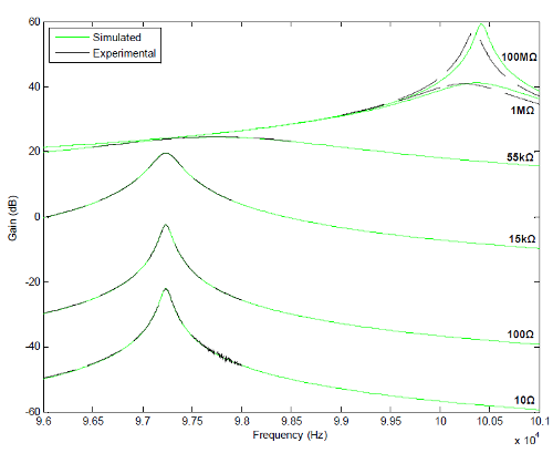
Frequency response of a Rosen piezoelectric transformer
Lumped parameter equivalent circuit modelling
The behaviour of most piezoelectric transformers, when they are excited about their resonant frequency, can be captured by the Mason equivalent circuit model. A Lumped Equivalent Circuit Model for the Radial Mode Piezoelectric Transformer, APEC 2009 derives an equivalent circuit model for a radial-mode step-down piezoelectric transformer. The model allows one to move between electrical and mechanical domains.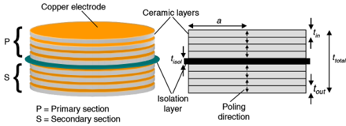
Radial-mode piezoelectric transformer
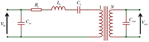
Mason equivalent circuit of a piezoelectric transformer
Zero voltage switching of inductorless driven piezoelectric transformers
The large input capacitance of the transformer can cause significant switching losses in the bridge MOSFETs if the commutation timings are not carefully controlled. An inductor can be connected in series with the transformer to mitigate these issues but this adds cost and volume. A better alternative is to use the transformer's resonating current to charge (or discharge) the input voltage during the bridge dead-time period to achieve zero voltage switching (ZVS) of the bridge MOSFETs. In Predicting the zero-voltage switching profiles of half-bridge driven inductor-less piezoelectric transformer-based inverters, IET Power Electronics 2012, a cyclic-mode model is derived and subsequently used to provide quantitative information regarding the ZVS ability of a piezoelectric transformer.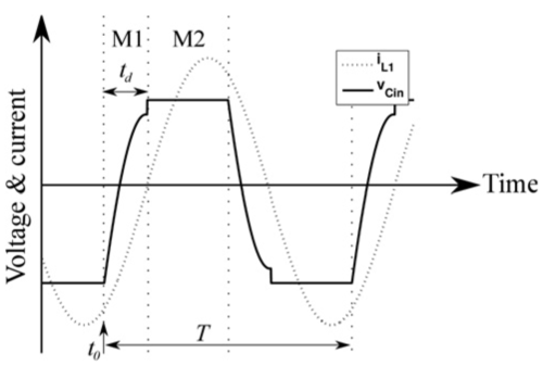
Waveforms for non-ZVS operation
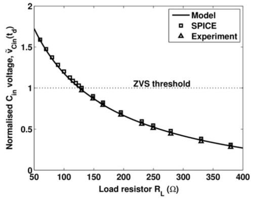
Maximum achieveable ZVS for a given load
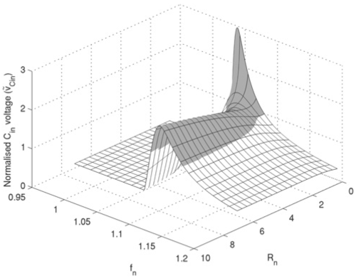
ZVS ratio as function of load and frequency
Design of piezoelectric transformers
Research on the ZVS ability of inductorless driven transformers revealed that ZVS could only be achieved for certain parameter combinations. Adapting the describing function techniques that I have previously applied to resonant converters allowed an equivalent circuit model for the ZVS process to be derived. By assuming the circuit operates at the resonant frequency it was shown that the ratio of input to output capacitance should be carefully chosen if ZVS is required. This design constraint is described in detail in Critical design criterion for achieving zero voltage switching in inductor-less half-bridge driven piezoelectric transformer based power supplies, IEEE Power Electronics 2015.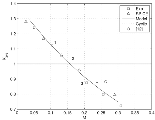
ZVS plot for a piezoelectric transformer
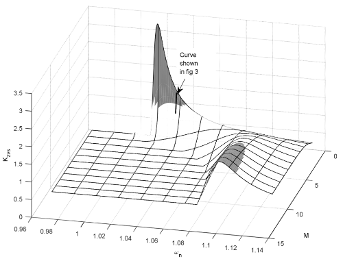
3D version of ZVS plot for a piezoelectric transformer